Noncontact Sheet Resistance Instrumentation
Many applications require objects that are sheets, wafers, panels, or plates of conductive or conductively coated material. For many of these applications, the resistance of the entire object (which could be a massive quantity) and/or the resistivity of the material are of secondary importance. Of primary importance is:
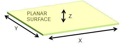
For use in these applications, sheet resistance (Rs) was created as a unit of measurement. The inherent value of sheet resistance is that it is a measure of the electrical properties of a material independent of the xy dimensions.
Sheet resistance is resistivity divided by the thickness of the material.
Eddy current meters can measure sheet resistance, thickness, resistivity, and more.
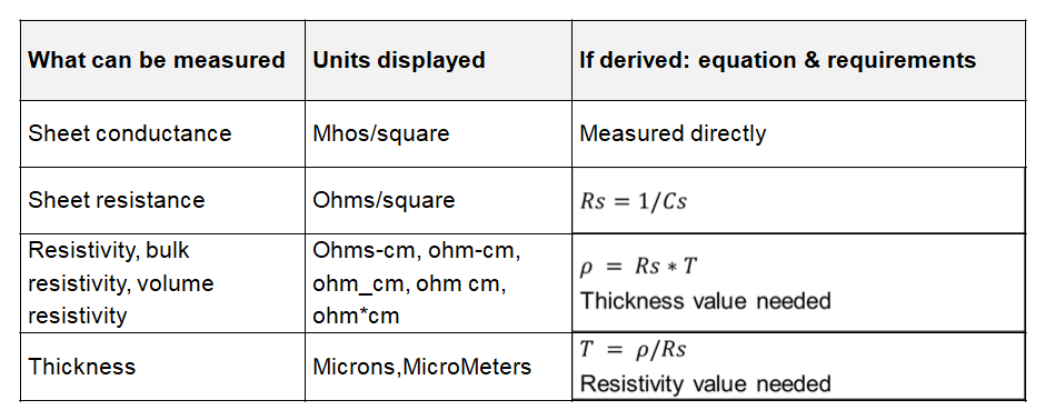
Delcom meters do not directly measure the resistivity of material—instead, they measure the sheet conductance of a conductive layer. However, if the material is of uniform thickness and if that thickness is known, a Delcom meter can be used to measure, record, display, and even map the material’s resistivity.
Delcom meters do not directly measure the thickness of material—instead, they measure the sheet conductance of a conductive layer. However, if the material is of uniform resistivity and if that resistivity is known, a Delcom meter can be used to measure, record, display, and even map the material’s thickness.
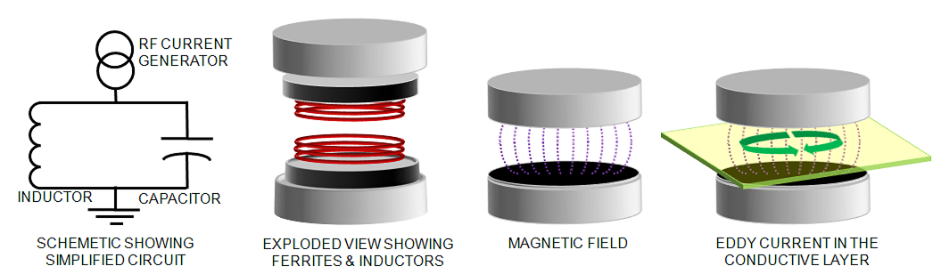
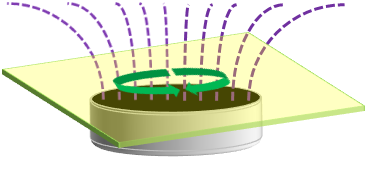
Request more informationThe essential element of an eddy current meter is an inductor in a ferrite core. Typically there are two inductor and core assemblies: one located above and one located below the material to be tested. A current—oscillating in the low megahertz (RF) region—flows through the inductor coils, generating an oscillating magnetic field. When a conductive material is introduced between the two inductors and into the magnetic field, a circular flow of electrons (an eddy current) begins to move in the conductive layer due to magnetic induction. The difficulty of maintaining this eddy current is used to deduce the sheet resistance of the material being measured.
Four point probes are the traditional instruments for determining sheet resistance. However, for many applications, Delcom’s eddy current meters are much more useful.
A Delcom eddy current meter:
Additionally, Delcom meters provide better repeatability and involve less cost and hassle than four point probes.
Request more informationEach Delcom sensor is calibrated against a National Institute for Standards and Technology (NIST) standard. This calibration takes place at the order of magnitude in which the sensor has the most significant digits. If all environmental factors are held constant and the calibration standard is inserted back into the sensor at exactly the same location, the meter will read the exact value of the standard. For this reason, Delcom guarantees 99.9% accuracy.
Any eddy current instrument should be nearly 100% accurate when measuring the standard that was used to calibrate it. Therefore any question from a user about the accuracy of a Delcom meter is really a question of whether the user’s standards match the standards used by Delcom. To make this question moot, any Delcom instrument can be quickly calibrated to a standard by the user upon receipt of the instrument. Calibration is a simple process that takes less than one minute.
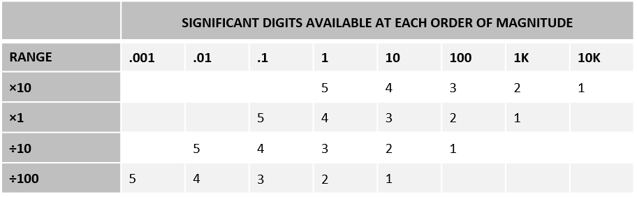
Resolution is a function of the significant digits available at each order of magnitude in a meter’s range.
Each meter’s range spans different orders of magnitude. Users should be familiar with the number of significant digits to be expected in each order of magnitude for the meter range they are using.
If the user is using a Delcom meter in mhos/square as the unit of measurement, keeping track of significant digits is easy: every digit is significant.
However, if a user is using a meter with ohms/square as the unit of measurement, care must be taken to keep track of—and understand—which digits are significant and which are not.
Each meter range spans different orders of magnitude. For this reason, the user should be familiar with the number of significant digits to expect in each order of magnitude for the meter range in use.
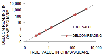
Linearity is the answer to the question, “If a meter is calibrated with a standard at one point in the meter’s range, how accurate will the meter be when reading other possible values in its range?”
Delcom calibrates each meter at the order of magnitude in which it has the most significant digits. Delcom then characterizes each meter’s linearity against NIST and other standards over the entire range of the meter. Delcom guarantees no more than 3% deviation from the true sheet resistance value of tested material. The graph below shows a Delcom sensor tested against 10 NIST, VLSI, and MSA standards.
Theoretically, a Delcom eddy current meter could measure from zero to infinity ohms/square. However, in reality, such a range is not practical or necessary. Over 30 years of research, Delcom has pushed eddy current technology so that the range of each of our sensors spans five orders of magnitude. This range is more than enough for most applications. Ranges are physically set in the sensors before they leave our factory, so the user must carefully choose the best range for the intended application prior to purchase.
| Instrument Range | Dynamic Range in ohms/square | Significant Digits Available at Each Order of Magnitude | ||||||||
|---|---|---|---|---|---|---|---|---|---|---|
| Low End | High End | 10k | 1k | 100 | 10 | 1 | .1 | .01 | .001 | |
| ×10 | 5 | 100,000 | 1 | 2 | 3 | 4 | 5 | |||
| ×1 | .5 | 10,000 | 1 | 2 | 3 | 4 | 5 | |||
| ÷10 | .05 | 1,000 | 1 | 2 | 3 | 4 | 5 | |||
| ÷100 | .005 | 100 | 1 | 2 | 3 | 4 | 5 | |||
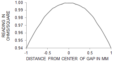
Eddy current meters usually have a top and a bottom inductor. Material reads higher sheet resistance in the exact middle elevation between the top and the bottom halves of the sensor. If the material is moved towards either the top or the bottom half of the sensor, the material will read a lower sheet resistance. Thus, it is imperative that material being measured is either introduced to the sensor at the magnetic center or that the sensor is calibrated to expect the material at another elevation and that the material is consistently inputted at that exact elevation. Delcom makes stages for benchtop sensors which aid greatly in achieving elevation consistency.
The S3 meter has a single-sided sensor. As such, the magnetic field is thrown off from the face of the sensor in a fountain-like pattern. As conductive material is elevated away from the face of the sensor, the field becomes less and less dense. This causes the sensor to read the material as having a higher and higher sheet resistance. This effect is called “lift-off.” Because of the lift-off effect, a single-sided sensor is only useful if the material elevation is carefully controlled. Elevation can be controlled in multiple ways.
The essential elements of a Delcom eddy current meter’s sensor are inductors in ferrite cores. An inductor/ferrite assembly exists in both the top and the bottom parts of the sensor (except for the single-sided S3 sensor). In general, given a certain diameter of a pair of inductor/ferrite assemblies, the smaller the gap between these sensor halves, the better the performance, and the larger the gap the poorer the performance. Thus, it is best to work with the smallest possible gap suitable to the desired application, and it is important to carefully choose the Delcom meter with the proper gap.
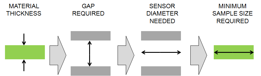
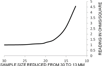
When material smaller than minimum sample size is measured, the meter will deliver a higher reading in ohms/square (more resistive) than the material would read if it was equal to or larger than the minimum sample size. Thus, measuring material smaller than sample size is not ideal—but it is possible. To measure smaller-than-minimum sample sizes, users must calibrate the meter to the size and shape to be measured, and must carefully maintain the exact same xy placement of all subsequent material inserted into the meter.
Eddy current meters experience reading drift correlating to drift in the surrounding temperature and variation in the meter’s own internal temperature. Delcom’s sheet resistance meters have been digitally temperature compensated to drastically reduce this drift. Users can observe certain practices to maximize the effectiveness of this digital compensation, as well as perform their own temperature compensation on the instruments if desired.
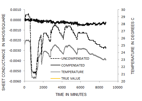
The readings of eddy current meters are affected by changes in temperature—both external and internal. Thus, it is ideal to turn on a Delcom meter a few hours before use, allowing time for the electronics to heat up and for the instrument to equilibrate to the ambient temperature. This is known as warm-up time.
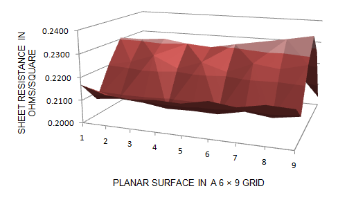
Request more informationMapping the sheet resistance or conductance of a sheet, panel, or wafer can be easily accomplished with a Delcom eddy current meter. Delcom’s user-friendly software facilitates the exportation of data to create helpful graphs and charts to analyze and display the resulting information.
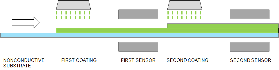
One useful advantage of Delcom’s eddy current meters is their ability to measure multiple layers. In order to read individual multiple layers, the user must read the first conductive layer, then coat the material again and take a second reading. The conductance of the second layer can be inferred by subtracting the value of the first reading from the value of the second reading.
In a benchtop setting, the user simply needs to measure the material after the first coating, coat the material again, and then measure the material a second time.
In an inline setting, this process can easily be accomplished by placing one sensor before the second coating process and a second sensor after the second coating process.
Eddy current instruments are technically not capable of measuring material smaller than the stated minimum sample size. However, with some effort, it is possible to use a Delcom meter to measure pieces of material smaller than the minimum sample size. In order to do this, the meter must be calibrated to the desired sample size and shape, a method must be used to consistently place samples in the sensor at the exact location each time, and all subsequent material samples must be the same shape and size as the sample used to calibrate the meter to the new smaller-than-minimum size.
Request more informationIn most cases, Delcom meters should never need to be recalibrated. However, users do have the ability to calibrate their instruments if desired. For example, a user may wish to introduce conductive samples into the instrument at an elevation within the gap of the sensor other than the magnetic center. In such a case, the user will need to follow a quick, simple process to calibrate the meter to this new elevation.
Request more information